

What Does a Smart Desktop Clock Need?
- Intermediate
- Article
- Ages 16+
- 7 min read

A smart desktop clock needs local timekeeping, a display, networking and a power supply. This proposed design uses an ESP32 board to obtain Internet time and weather for a selected location. The clock face should remain useful during a network outage and clearly distinguish current information from older data.
Contents
- Clock face and controller
- Network services
- Power assembly
What you will learn
- Separate local timekeeping from network requests.
- Specify hardware for compact and large displays.
- Define a useful first version that is straightforward to program and test.
Before you start
Read about the ESP32 board and the Arduino loop, and understand GPIO.
How do the components exchange information?
The controller gives the display a snapshot of available information, with a separate status for each source. ESP32 station mode joins a home Wi-Fi network. SNTP sets system time from an NTP server response. The weather API accepts coordinates and requested variables and returns JSON for the firmware to process.
In the proposed design, time can be unknown, synchronized or continuing locally since its previous synchronization. Weather can be missing, current or stale. Losing Wi-Fi changes network status; it should not erase a running clock or replace a missing temperature with an invented reading.
Startup begins by loading settings and drawing the clock face. The firmware then attempts a connection, synchronizes time and requests weather. Each successful result replaces its own data. A failed request leaves a stale indication while keeping the light button and settings available.
- Local time
- Weather
- Independent states
- Rendered face
Which hardware belongs in the first version?
Start with a board with suitable software support, a supported monochrome graphic LCD and USB power, then investigate the battery version. These are choices for this illustrative example rather than a tested bill of materials.
| Component | Proposed starting point | Check before purchase |
|---|---|---|
| Controller | An ESP32 board using the Arduino core | Board support and enough peripheral pins |
| Display | A monochrome graphic LCD with library support | Active area, controller, interface, voltage and backlight |
| Timekeeping | System time after network synchronization | Whether time must survive complete power loss |
| Location | A place selected during setup | Store its name, coordinates and time zone together |
| Power | USB first, then a complete battery assembly | Load current, power routing and operation during charging |
| Controls | Menu, + and − buttons | Clear press, hold, save and cancel behavior |
| Sound | A sound module suitable for the board | Control method and load current for the selected module |
| Updates | Reserve flash space for OTA from the start | Room for the new build and a recovery path |
The compact face gives most space to the time. A larger version keeps the hierarchy while increasing actual character size and spacing. Evaluate it from the intended chair or bed rather than choosing solely by the display diagonal.
Decide the timekeeping requirement early. The chip RTC timer keeps time through sleep but resets on a power-on reset. Starting with correct time after complete power loss and without networking requires an external real-time clock with backup power compatible with the selected module.
- Compact version
- Distance-reading version
How can the firmware stay manageable?
The first version includes time, location setup, weather, power status and a button-configured alarm. Add OTA for later features and bug fixes once wired programming works reliably. The proposed software uses the Arduino core and a library supporting the actual display controller. Rendering receives a shared data snapshot instead of making network requests or reading the battery itself.
Separate timekeeping, weather, settings and rendering. A different display goes through a display adapter and layout profile. Hardware settings record the drawing area, font and connections; user settings contain the place and lighting preference.
Build in stages: draw a fictional clock face, read local time, synchronize it, add weather and finally introduce sleep. Keep working behavior from each stage. Beginning with power optimization makes display problems harder to distinguish from wake-up and network problems.
Useful acceptance criteria are continued time display during an outage, retained location after a restart and visible weather failures. Changing screen sizes should leave data acquisition unchanged. Battery endurance becomes a result only after measuring the assembled device.
In the proposed extension, the alarm reads valid local time and a saved schedule without waiting for weather. Three buttons open the menu, edit individual fields and confirm changes; holding Menu cancels edits. Wi-Fi setup deliberately opens phone-based entry for longer information. The distance-view version uses the same controls and clearly shows whether the alarm is enabled.
The OTA component receives an Update menu request, displays versions and changes, and waits for installation confirmation. The design retains a previous application for recovery where the bootloader supports it and that path has been tested. Defer updates during alarm activity or near an occurrence. Check settings, rendering and buttons after restart before accepting the build. The firmware article develops this sequence.
- Data and status
- Display adapter
- Selected screen
Real-world example
A family member configures a bedside clock's location from a phone. With networking available at startup, the clock obtains time and weather and shows large time characters beside an outdoor weather symbol. This is a proposed operating sequence.
The router switches off overnight. Local timekeeping continues while the weather becomes visibly stale. When networking returns, a successful update removes that indication. If all power had been removed without a backup RTC, the face would show that time is unknown until it can be set again.
Common misunderstandings
Wi-Fi requires a permanent connection. Connection scheduling belongs to the firmware. This design separates reading time from network update sessions.
Any monochrome LCD is interchangeable. Check the controller, interface, voltage and lighting against the actual module. A larger diagonal does not establish compatible wiring or library support.
Frequently asked questions
Does a desktop clock need GPS?
This design obtains coordinates from a place selected during setup. Add GPS only if the actual use case requires the clock to determine a changed location itself.
Is a private server needed to begin?
A prototype can contact time and weather services directly. A product also needs a review of service terms and firmware updates.
Can small and large versions share software?
They can share data and state handling. The display controller, fonts and layout still require their own configuration and checks.
Terms in this article
English and Vietnamese terms, with the meanings used here. Hover, tap or Tab to a term with a dotted underline for an explanation as you read.
- Simple Network Time ProtocolSNTP
- A protocol used to synchronize system time with a time server.
- real-time clockRTC
- Local timekeeping hardware whose ability to keep running depends on the hardware and its power supply.
This article is not marked as viewed
Spotted something wrong or unsafe?
Tell the administrator by email. The message already has the article title and address.
You may also like
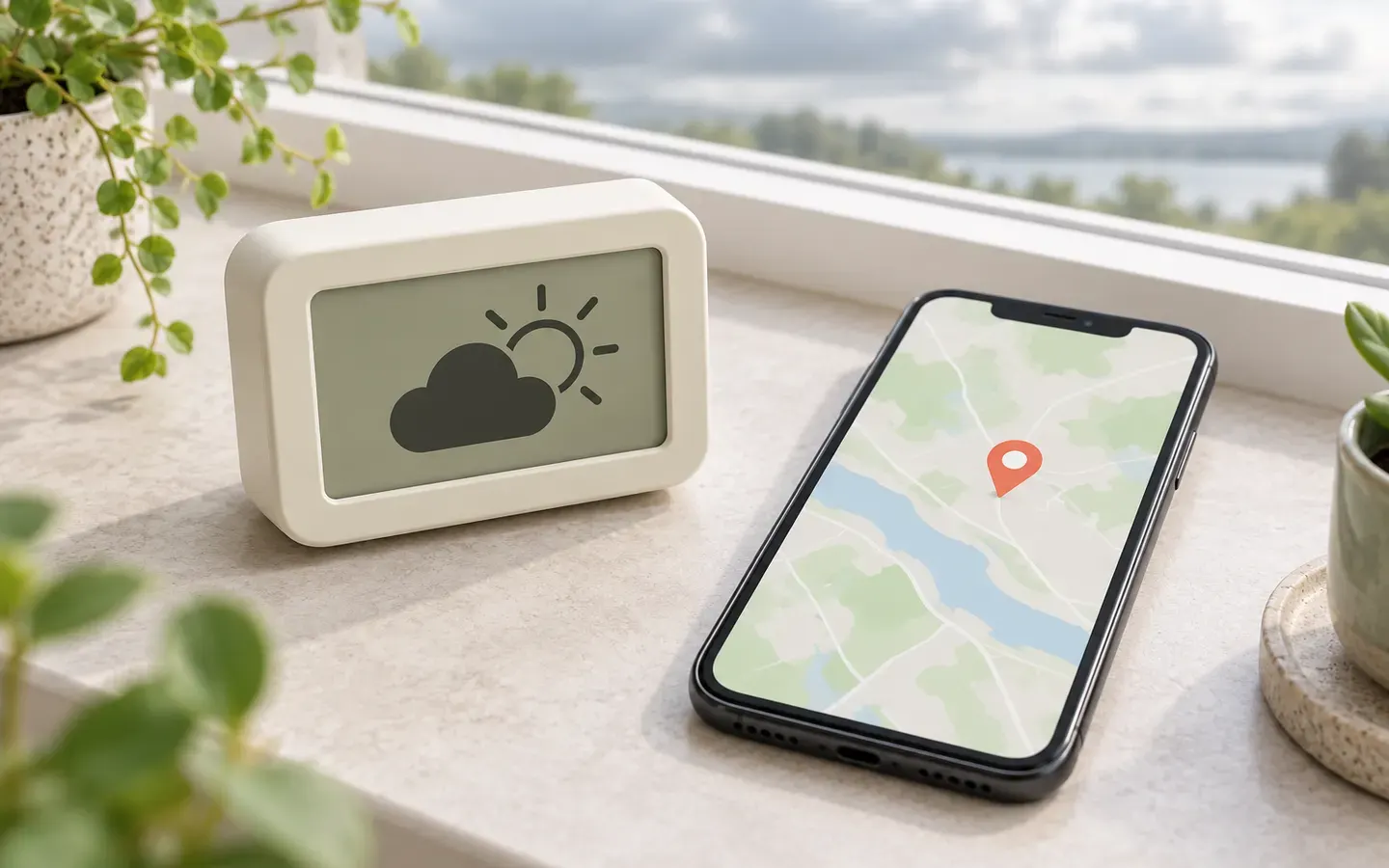 Intermediate
Internet Time and Local Weather for a Clock
Synchronize time, select and store a location, and handle stale weather without confusing outdoor conditions with room temperature.
Internet of Things (IoT)7 min read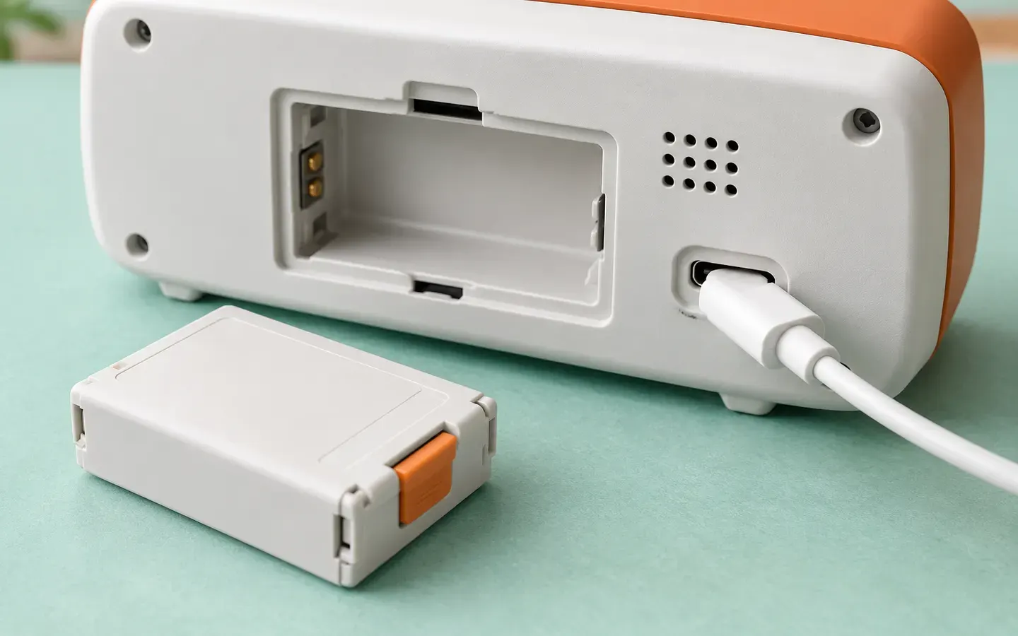 Intermediate
USB, Rechargeable Power and LCD Clock Runtime
Budget energy for an LCD clock, distinguish charging from power-path control, and measure lighting, networking and sleep costs.
Internet of Things (IoT)7 min read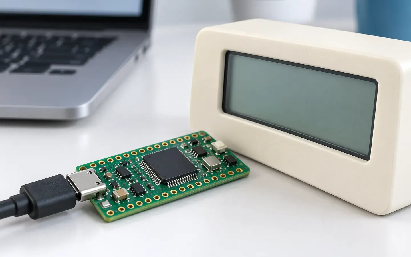 Intermediate
Writing Simple Clock Firmware with Arduino
Design clock firmware with button menus, saved alarms and OTA updates, including network failures, image verification and recovery.
Internet of Things (IoT)14 min read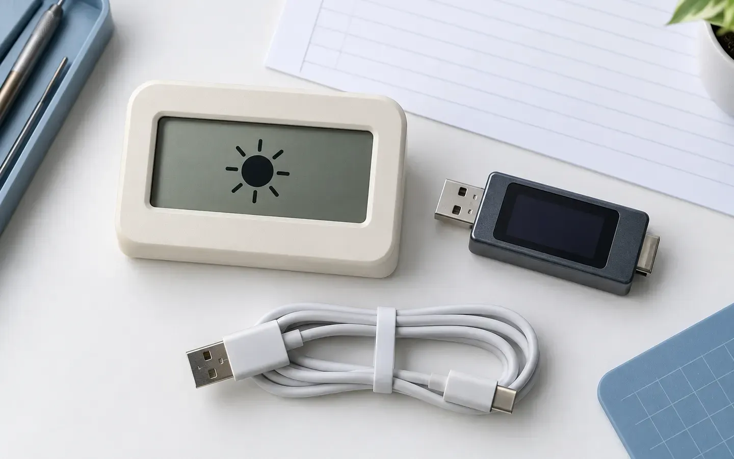 Intermediate
Testing an LCD Clock Before Enclosure Design
Test clock time, alarms, button menus, OTA and power transitions; check settings recovery, readability and energy before enclosure design.
Internet of Things (IoT)9 min read


Sources
These sources are written for older readers. If they feel hard, read them with an adult.
- Wi-Fi API — Arduino-ESP32(opens in a new tab)
EspressifTier C: other sourcesRead on November 1, 2026
- System Time — ESP-IDF(opens in a new tab)
EspressifTier C: other sourcesRead on November 1, 2026
- Weather Forecast API(opens in a new tab)
Open-MeteoTier C: other sourcesRead on November 1, 2026