

What Roles Can a Chip Pin Have?
- Starter
- Article
- Ages 10+
- 5 min read

Contents
- Chip body
- Input pins
- Output pins
- Power and ground pins
What you will learn
- Say what a chip pin is and what it connects the chip to.
- Tell input pins from output pins and see how an output pin sets its voltage level.
- Name roles beyond general-purpose input/output: power, ground, clock and debugging.
Before you start
No prior knowledge is needed. The article uses a microcontroller as the example because its documentation describes each kind of pin clearly.
What is a chip pin?
A pin is a hardware connection between the chip and its external world, according to the University of Texas at Austin microcontroller textbook. Most pins are used for input or output, and a group of input/output pins is called a port.
A General Purpose Input Output (GPIO) port is a collection of input/output pins that software uses to read data from input pins and write data to output pins. That is why one chip can be wired to buttons, lamps and sensors without changing the hardware inside it.
- Button
- Chip
- LED
- Battery
How do input pins and output pins differ?
An input pin brings information from the outside world into the computer, and an output pin sends information from the computer out. Initialization software is where a pin is set to be an input or an output.
An output pin sets its voltage level with two switches inside it, according to the University of California, Berkeley GPIO notes. When the output is set to level 1, the switch on the supply side closes and the pin connects to the supply. When it is set to level 0, the switch on the ground side closes and the pin connects to ground. A voltage near 0 (ground) is read as logic 0.
Open drain mode uses only the ground-side switch. The pin is pulled to ground when set to 0 and left open, connected to nothing, when set to 1.
On the input side, a button wired between a pin and ground gives a clear level 0 when pressed.
- Output at level 1
- Output at level 0
- Open drain at level 1
Data on a pin also takes several forms. In serial form, bits pass through one pin one after another. In analog form, data is encoded as a voltage, current or power on a single pin.
What do pins beyond GPIO do?
Besides input/output pins, a microcontroller uses some pins for power, clock and debugging. Power pins receive the electricity supplied to the chip. The GND pin is the common ground for power and logic, so every other voltage level is measured against it.
A clock pin connects to the source of the chip's rhythm. A debugging pin connects to the cable used to load and inspect a program. These two jobs are the uses of pins beyond input/output that the documentation names.
- Power
- Ground
- Clock
- Debugging
- Chip
Real-world example
Think of a portable radio. The battery compartment supplies power, the dial brings your wish in, and the speaker sends sound out. Each part touches the outside world at its own place. Chip pins share out their work the same way, only much smaller and arranged by software.
This is only a comparison to help you remember. The number of pins and the job of each depend on the specific chip.
Common misunderstandings
Power and ground pins supply energy and establish the voltage reference. Clock pins provide timing; the debugging interface serves program loading and inspection.
Level 0 does not mean the pin is disconnected. On an output, level 0 connects the pin to ground. Only in open drain mode, when set to 1, is the pin left open.
A general-purpose input/output pin does not come with a fixed role. Initialization software sets it as an input or an output.
Frequently asked questions
What is the GND pin?
GND is the common ground for power and logic. The Berkeley notes describe it this way in a board's power pin table.
What is GPIO?
GPIO is a general-purpose input/output port, a collection of input/output pins. Software uses it to read input pins and write output pins.
How does a button give a level 0?
One side of the button goes to the input pin and the other to ground. Pressing it connects the pin to ground and gives a clear level 0.
Summary
- A pin connects the chip to the outside world, and most pins are used for input or output.
- An output pin sets level 1 or 0 by connecting to the supply or to ground; open drain uses only the ground-side switch.
- Some pins provide power, ground, clock and a debugging interface.
Terms in this article
English and Vietnamese terms, with the meanings used here. Hover, tap or Tab to a term with a dotted underline for an explanation as you read.
- pinchân
- A hardware connection between the chip and the outside world.
- microcontrollervi điều khiển
- A computer on a single chip, with pins that connect it to the outside world.
- input pinchân vào
- A pin that brings information from the outside world into the computer.
- output pinchân ra
- A pin that sends information from the computer out to the outside world.
- General Purpose Input Output (GPIO)GPIO
- A port of input/output pins that software uses to read and write.
- ground (GND)GND
- The common ground of power and logic.
- open drainhở máng
- An output mode that only pulls the pin to ground or leaves it open.
- portcổng
- A group of input/output pins.
This article is not marked as viewed
Spotted something wrong or unsafe?
Tell the administrator by email. The message already has the article title and address.
More in this topic
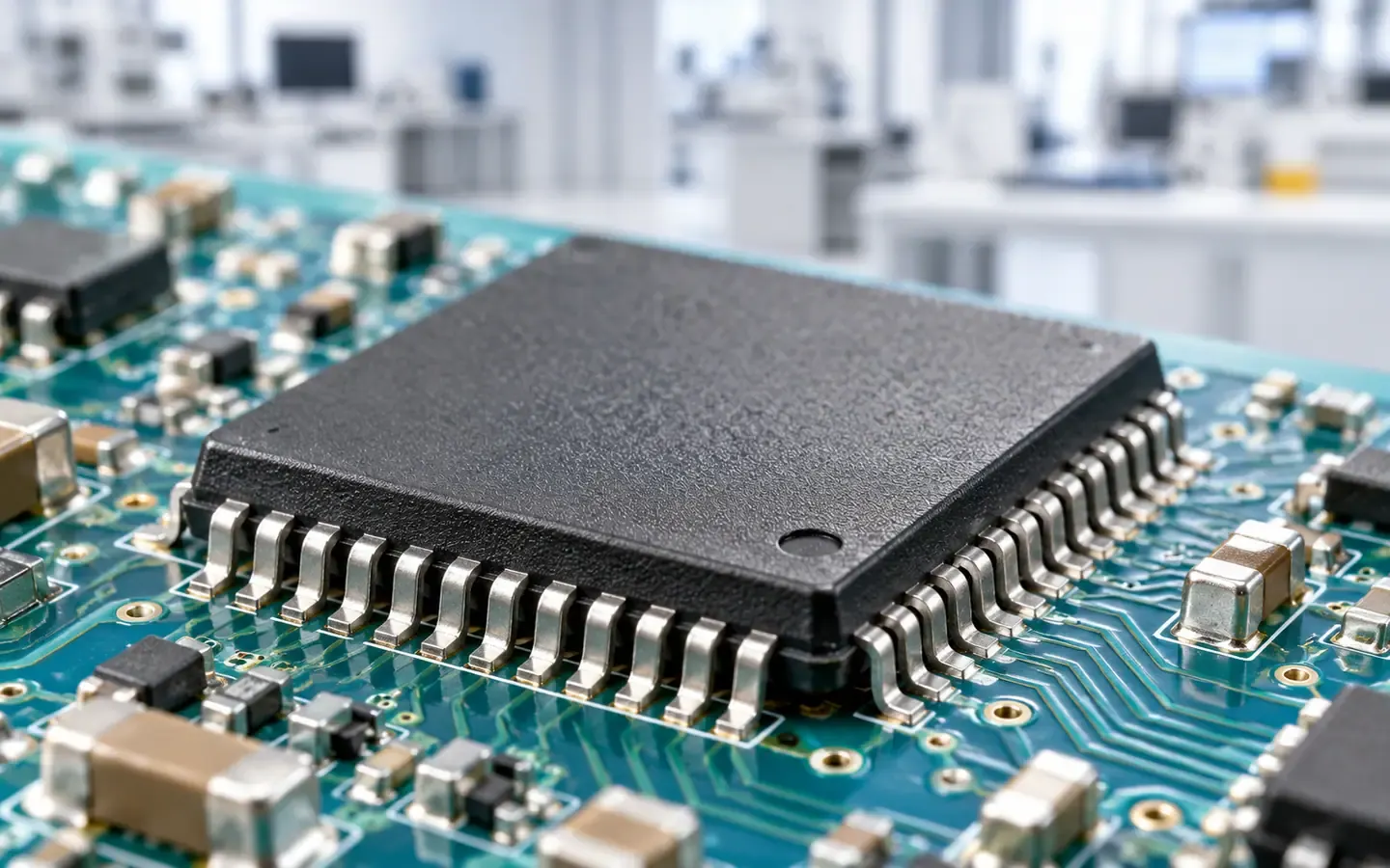 Starter
What Is a Microchip?
Understand microchips, transistors and chip packages through a phone example, and distinguish a semiconductor material from a finished circuit.
5 min read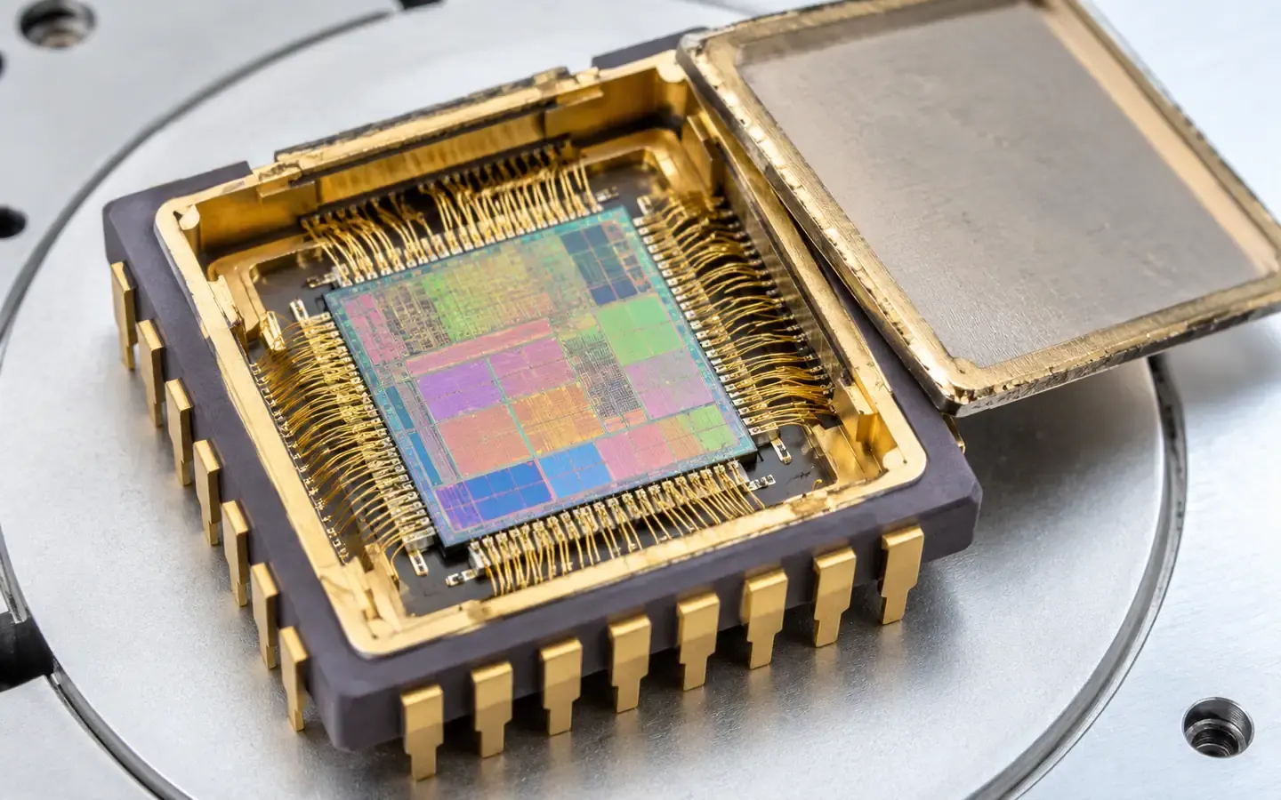 Starter
What Is Inside a Microchip?
Explore the semiconductor base, transistors and chip package, and see how these parts form a component used in electronic devices.
5 min read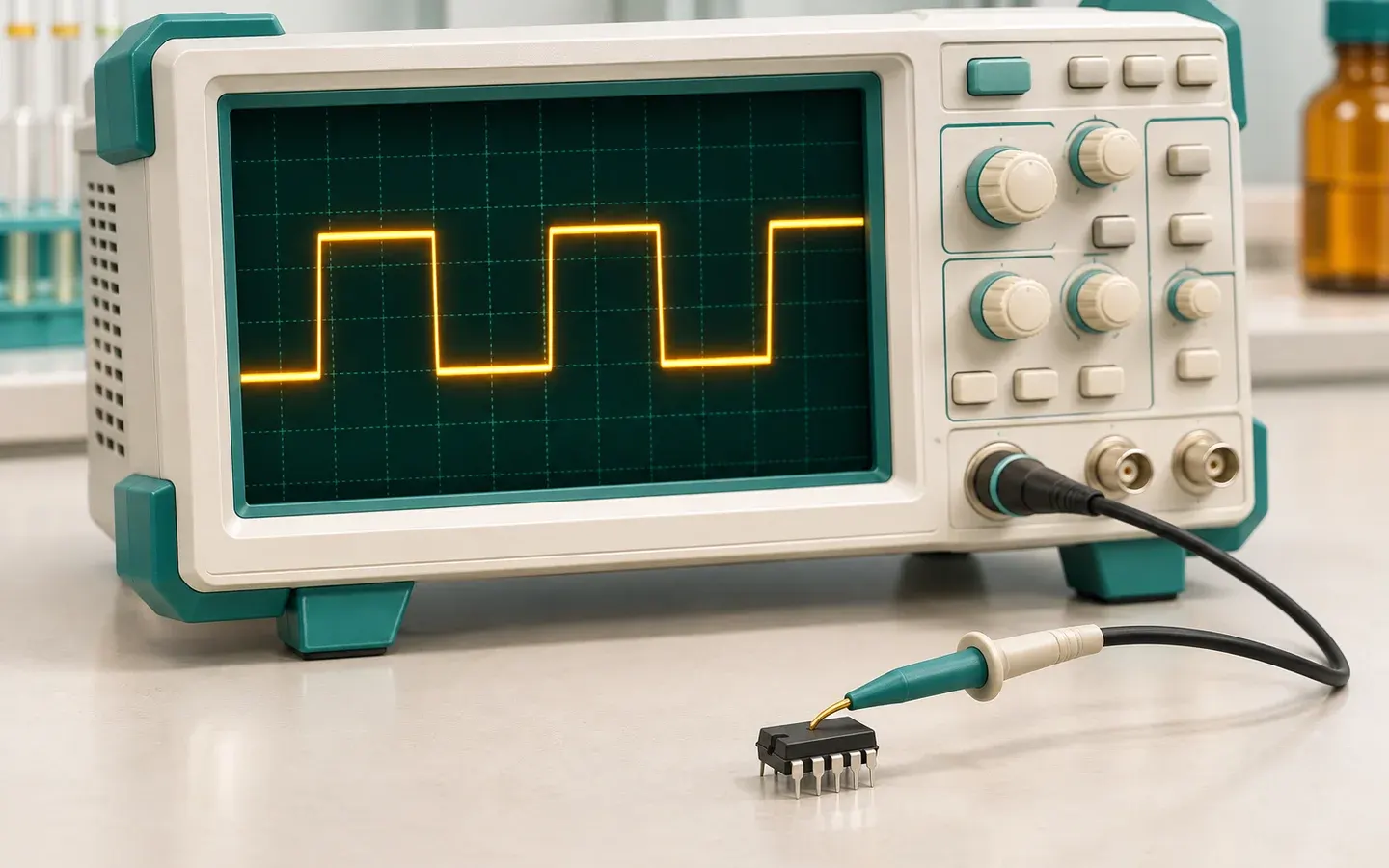 Starter
How Do Voltage Levels Represent Digital Signals?
See how chips read HIGH and LOW from voltage, how logic families set thresholds, and how a transistor switch flips a level.
5 min read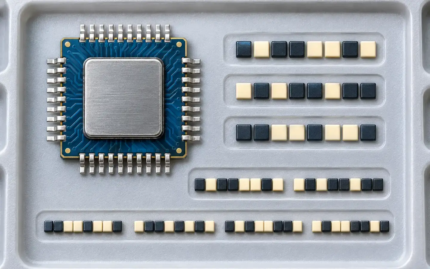 Starter
How Do Bits, Bytes and Machine Words Differ?
Compare bits, nibbles, bytes and machine words by length, and understand why a byte has a fixed size while word length depends on the design.
5 min read


Sources
These sources are written for older readers. If they feel hard, read them with an adult.
- Introduction to Interfacing (Valvano, MSPM0 e-book ch. 2)(opens in a new tab)
University of Texas at AustinTier A: government, standards or research bodiesRead on November 4, 2026
- General Purpose Input/Output (GPIO), EECS course notes(opens in a new tab)
UC BerkeleyTier A: government, standards or research bodiesRead on November 4, 2026