

Which Sensors Stop a Small Robot Falling or Colliding?
- Intermediate
- Article
- Ages 16+
- 7 min read

A small mopping robot relies on six close-range sensor groups: cliff sensors looking down at the floor, a bumper, time-of-flight (ToF) distance sensors, wheel encoders, an IMU and motor-current sensing. Each answers its own question about the floor, obstacles or motion. The reflex layer on the robot always puts cliff and bump signals first.
Contents
- Flat round robot body
- Downward-looking cliff sensors
- Bumper on the front rim
- ToF sensor and its narrow beam ahead
- Wheels
- IMU at the centre of the body
- Encoder discs on the wheels
What you will learn
- Explain how a cliff sensor and a time-of-flight sensor measure, and when they are fooled.
- Say where each sensor sits on a low round body.
- Rank sensors when several fire at once, then check whether a sensor can still be trusted.
Before you start
You only need to know that robots use sensors to sense their surroundings, for example from the article How Do Robots Use Sensors to Understand Their Surroundings?. The designs below are illustrative models, not results from a real robot.
How does a cliff sensor see the edge of a step?
A cliff sensor checks whether the floor is where it should be under the rim of the body. A patent on a cleaning robot describes intersecting a detector's field of view with a directed beam's field of emission at a predetermined region. If the floor does not occupy that region, the same document says a stair or another obstacle is present and the robot is directed away. The aim is to stop an autonomous cleaning robot driving off a stair or an obstacle that is too high.
A reflective infrared module does the same job with simple hardware. Pololu's module carries one infrared LED and phototransistor pair, and a lower output voltage means greater reflection. The robot compares that voltage with a threshold. The threshold is a design choice, tuned on the real floors of the home.
The same measurement creates the weakness. Another patent notes that some proximity sensors perform unacceptably on darker, less reflective surfaces. A black rug can therefore look like a drop. By the same principle, dust over the sensor window weakens the signal, and the robot reads that as lost floor.
- Ordinary floor
- Robot body
- Tilted emitter and receiver
- Emitted beam meeting the floor
- Step edge, no floor at the meeting point
- Dark rug strip
- Weak return beam from the dark rug
What do the bumper and the ToF sensor catch?
The bumper reports that something has touched the body, while the ToF sensor reports how far away something is. One patent describes a bumper that detects events in the robot's drive path, and a random-bounce cleaning robot travels straight until it bumps into an object, then turns away. The bumper is the last stop: when other sensors misjudge, a hard object is still caught on contact.
A time-of-flight sensor measures how long the light takes to bounce back to the sensor. The beam of a small ToF module is very narrow, so Adafruit's documentation says it reports the distance of only the surface directly in front. For a round body, one ToF sensor sees one direction and misses a chair leg off to the side.
The table lists what tends to mislead a ToF sensor and what the robot should do. The action column is a design proposal.
| Object ahead | What happens to the ToF reading | What the robot should do |
|---|---|---|
| Dark object | Range-dependent bias and substantially larger uncertainty | Slow down and let the bumper be the last stop |
| Shiny metal, wall corner | The same paper recalls that reflective materials and corners caused artifacts in the point cloud | Do not trust one reading; take several |
| Clear plastic or glass | The sensor measures the distance to the transparent barrier, not the object | Rely on the bumper to learn that something is there |
- Round robot
- Bumper
- Narrow ToF beam
- Glass pane
- Box behind the glass, not seen
- Chair leg outside the beam, touching the bumper
- Return signal from the glass surface
What do encoders, the IMU and motor current say about motion?
These three sensors do not look outward; they report how the robot is moving. A wheel encoder counts the turns of each wheel, and the differential drive controller computes odometry from hardware feedback. An IMU is a module combining an accelerometer and gyroscope with six measurement axes in total: the gyro reports turning, and the accelerometer reports tilt or a knock. A current sensor such as Pololu's Hall-effect current-sensor board shows how hard a motor is pulling.
Their value comes from cross-checking. In the illustrative design, rising current while the encoder stands still means a wheel is held, so the robot is jammed. During a commanded turn, the model compares expected rotation from both encoders with the IMU to find disagreement; this only suggests slip or a sensor error. In straight travel the wheels turn without a heading change, so those two observations alone do not prove slip. The tank has a level sensor, for example a float or a probe, so the robot heads home before the pump runs dry.
| Sensor | What it tells | Sign it has failed |
|---|---|---|
| Wheel encoder | How far each wheel turned | One wheel stays still despite a command |
| IMU | Turning, tilt, knocks | Readings drift while the robot is still |
| Current sensing | Motor effort | Long high current when the robot is not jammed |
- Wheel encoder standing still
- Motor current at a high level
- IMU seeing no rotation
- Robot blocked by an obstacle
- Cross-check lines between the sensors
Which sensor wins when several fire at once?
In the illustrative design, possible lost-floor or bump signals first require a stop. A later reverse or turn is permitted only when sensors still confirm a clear escape direction. The reflex layer runs on the robot's own microcontroller and never waits for the computer. The proposed order, highest first:
- Cliff: stop; reverse or turn only with a confirmed escape direction.
- Bumper: stop and sidestep.
- Current and encoder feedback suggest a jam: cut the pump, then attempt a bounded escape only with safe rear clearance.
- ToF: slow down, turn early.
- Encoder and IMU: update the position estimate.
To know whether a sensor can still be trusted, the robot tests itself at the dock before each run. Placed on a known floor, every cliff sensor must report floor. Lifted, they must report no floor. A still IMU must not report rotation. A sensor that fails the test keeps the robot at the dock and sends a report to the computer.
- Cliff, highest priority
- Bumper
- Motor current and encoder report a jam
- ToF
- Encoder and IMU update position
- Bracket: the reflex layer on the robot
- Robot on the dock, passed the self-test
Real-world example
This is a design scenario. The robot drives along a hallway to the top of a staircase. The front cliff sensor loses the floor signal, the reflex layer stops both wheels, backs up and turns, then reports the edge position to the computer.
Later the robot enters a bedroom with a black rug. Two cliff sensors report lost floor at once. The encoders show the robot was driving level and the IMU sees no tilt, so the robot suspects a dark floor and not a real drop. It backs away, marks the area and asks the computer to let a person look. It does not carry on over the doubtful patch.
Common misunderstandings
A cliff sensor sees every kind of edge. It only measures reflected light, so a dark floor is mistaken for a drop, and so is dust on the sensor window.
A ToF sensor sees everything ahead. The narrow beam misses objects to the side, and glass can make a reading fail to represent the intended object; never assume every ToF sensor detects glass. The bumper is still needed.
With an IMU, encoders are unnecessary. They provide complementary measurements; comparing them finds disagreement, not every possible kind of slip.
Frequently asked questions
Does a mopping robot need cliff sensors?
Yes, if the home has stairs or high edges. According to the cleaning-robot patent, such a system prevents the robot from driving off a stair or an obstacle that is too high.
Why can a mopping robot be afraid of black rugs?
Because a cliff sensor measures reflection, and a dark surface reflects little, so it can look like a drop. Cross-check with the IMU and encoders.
Does a small robot need both a ToF sensor and a bumper?
Ideally both. The ToF sensor warns early but sees one direction; the bumper catches what the ToF sensor misses.
Summary
- A cliff sensor measures reflection toward the floor, so dark floors can fool it; the bumper is the last stop for hard objects.
- A ToF sensor gives distance in one direction and errs on dark objects, glass and shiny metal.
- Cliff and bump signals have the highest priority, and the robot tests its sensors at the dock before each run.
Terms in this article
English and Vietnamese terms, with the meanings used here. Hover, tap or Tab to a term with a dotted underline for an explanation as you read.
- cliff sensorcảm biến chống rơi
- A sensor that looks down at the floor to detect where it ends, such as the edge of a stair.
- bumpercản va chạm
- A part on the front rim of the body that reports the robot has touched an object.
- time-of-flight sensorcảm biến thời gian bay
- A sensor that measures distance from the time light takes to travel to an object and back.
- wheel encoderencoder
- A sensor that counts the turns of a wheel.
- inertial measurement unitIMU
- A module combining an accelerometer and a gyroscope to measure tilt, knocks and rotation.
- odometry
- An estimate of the robot's position from wheel feedback.
- reflex layerlớp phản xạ
- The control part on the robot that reacts at once to safety signals without waiting for the computer.
This article is not marked as viewed
Spotted something wrong or unsafe?
Tell the administrator by email. The message already has the article title and address.
You may also like
 Intermediate
How Does a Dock Recharge and Refill a Mop Robot?
A mop robot docks in stages, charges through contacts, then refills its tank; this covers guidance, contact checks, water levels and sharing a dock.
Robotics7 min read Intermediate
How Long Does a Small Mop Robot Run per Charge?
The energy budget of a small mop robot: load split, usable capacity, charge estimates and the reserve needed to reach the dock.
Robotics7 min read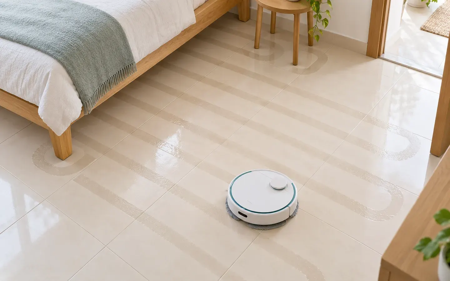 Advanced
What Path Lets a Robot Mop Cover a Whole Room?
How a mop robot covers a whole room: cells around obstacles, back-and-forth passes, a map of cleaned cells, drift correction and blocked cells.
Robotics8 min read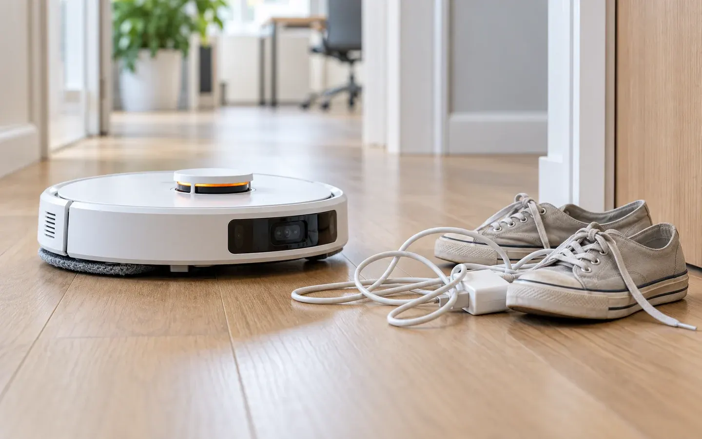 Intermediate
How Can a Mop Robot Spot Clutter and Alert a Person?
How a mop robot merges bumps, jams, unreachable cells and still frames into a clutter score per zone, then alerts a person at the right time.
Artificial intelligence7 min read


Sources
These sources are written for older readers. If they feel hard, read them with an adult.
- On the Characterisation of the Time-of-Flight VL53L5CX Sensor by STMicroelectronics for Indoor Robotics Applications(opens in a new tab)
PubMed CentralTier A: government, standards or research bodiesRead on November 2, 2026
- US7430455B2 Obstacle following sensor scheme for a mobile robot(opens in a new tab)
Google PatentsTier C: other sourcesRead on November 2, 2026
- US8862271B2 Proximity sensing on mobile robots(opens in a new tab)
Google PatentsTier C: other sourcesRead on November 2, 2026
- US10594920B2 Glass detection with time of flight sensor(opens in a new tab)
Google PatentsTier C: other sourcesRead on November 2, 2026
- Adafruit VL53L0X Time of Flight Distance Sensor Breakout(opens in a new tab)
AdafruitTier C: other sourcesRead on November 2, 2026
- QTR-1A Reflectance Sensor (2-Pack)(opens in a new tab)
PololuTier C: other sourcesRead on November 2, 2026
- ACS711KEXLT-15AB-T Current Sensor Carrier(opens in a new tab)
PololuTier C: other sourcesRead on November 2, 2026
- MPU6050 6-DoF Accelerometer and Gyro(opens in a new tab)
AdafruitTier C: other sourcesRead on November 2, 2026
- Diff Drive Controller (ros2_controllers)(opens in a new tab)
ROS 2 DocumentationTier A: government, standards or research bodiesRead on November 2, 2026